
3 cutting process performance
Milling, boring, drilling and tapping of aircraft components of different shapes and sizes, such as laser rapid prototyping TA15 titanium alloy I-beams, joints, frames, etc., show that the cutting process performance of laser rapid prototyping titanium alloy and forged titanium The alloy is comparable and exhibits good cutting process stability. This is related to the insensitivity of the microstructure of the laser rapid prototyping titanium alloy to the shape, size, wall thickness and the like of the part.
It has been found that the following two aspects are unique in the laser rapid prototyping of titanium alloy components, and care must be taken when formulating the cutting process.
(1) Laser rapid prototyping of titanium alloy components Before the roughing, the blanks must be carefully scribed and positioned, and if necessary, the test passes. Because the rapid prototyping of the laser obtains a "near-final" blank with a certain dimensional accuracy, the machining allowance is much less than that of the forging, and at the same time, the dimensional relationship has been formed between the parts, so the external profile is required before processing. The key parts are fully detailed and scribbled to determine the reference in the three-dimensional directions of X, Y and Z to ensure that all surface layers on the finished part (including the corrugated original surface and the surface oxygenized layer formed during heat treatment) Can be processed and removed.
For example, in the process of laser rapid prototyping of a large aircraft complex of TA15 titanium alloy (there are a large number of crisscross rib structures), the first roughing is only positioned in the outer dimensions, resulting in a very large machining allowance on the side of the individual ribs. Large, while the corrugated surface on the other side has not been processed and flattened; after increasing the work of the fitter and the test pass, the machining reference is optimized and adjusted so that each part has a certain machining allowance.
(2) When rough machining of laser rapid prototyping titanium alloy components, the first large feed depth strategy should be adopted for the first feed, that is, the cutting edge should be prevented from directly cutting the corrugated relief layer, the surface bonding oxide particles and the heat treatment oxygen permeation layer. In the initial research work, if the depth of the first infeed is small, the noise is sharp and the flutter is obvious during roughing, and the chipping phenomenon often occurs, and the tool wears faster (Fig. 6(a)); after increasing the depth of cut, the blade After cutting into the surface oxide layer, the cutting effect is significantly improved (Fig. 6(b)).
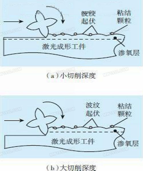
Fig. 6 Schematic diagram of rough processing of laser rapid prototyping TA15 titanium alloy
4 Laser rapid prototyping of large components of TA15 titanium alloy aircraft
4.1 Milling roughing
Prior to roughing, the laser-formed "near-final" blank is scribed on the bench platform to synthesize the relative positions of the ribs and rims below the web and the positional relationship between the two joints above the web. The machining standard is determined and the test pass is performed to ensure the uniformity of the machining allowance.
Since the roughing stage is to remove the machining allowance quickly and control the overall deformation of the part as the main target, and also take into account the ultrasonic testing requirements after rough machining (such as surface roughness Ra3.2, one-side machining allowance ≥1.5mm, etc.), The process scheme adopted is a combination of high cutting speed, high feed rate and small cutting amount. The cutting and cutting are performed as far as possible by using continuous spiral and circular path for tangential feeding to ensure constant cutting conditions.
The laser rapid prototyping TA15 titanium alloy I-beam is rough-processed by high-speed machining such as spiral, and the matching of cutting efficiency and surface quality is obtained. The physical photograph of the rough processing is shown in Fig. 7.
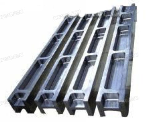
Fig. 7 Laser rapid prototyping of TA15 titanium alloy I-beam
| Previous page | 1 | 2 | 3 | 4 | 5 | Next page |
Globe Valves and angle valves are designed for throttling or regulating flow in commercial and industrial applications. Bronze, cast iron, or cast ductile iron materials. Threaded, flanged, or solder end connections.
Angle valves for use in commercial and industrial applications. Typical services include hot and cold water, HVAC, steam, compressed air, gas and other general utility services.
Vacuum angle valve is used for turn on or shut off the airflow in the vacuum pipeline, the applicable media is air and non-corrosive gases.
It has two structures, one is angle type and another is a 3-way type within an ISO-KF or ISO-F various flange end pre-pump port.
a) Small diameter (≤DN50) valve body are precision investment casting.
b) Large diameter (> DN50) valve body are molding shaped seamless steel or steel plate.
c) Bellows sealed structure can withstand 150ºCtemperature, metal sealed structure can withstand 450ºCtemperature.
d) Can install on any position to control the airflow in the vacuum pipeline, as an on-off valve purpose
Angle Valves, Angle Globe Valves, Brass Angle Valve, Zinc Angle Valve
ZHEJIANG KINGSIR VALVE CO., LTD. , https://www.kingsir-valves.com