The plastic button cage product structure is shown in Figure 1, wherein Figure 1a is a square button cage and Figure 1b is an oval button cage.
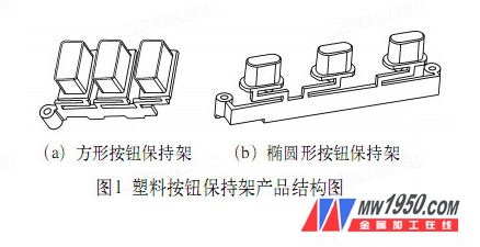
Its material is PP, which is one of the most commonly used general-purpose plastics. It has good mechanical properties, electrical insulation properties, heat resistance and chemical stability, and is inexpensive. It is commonly used to make structural parts of household appliances and other daily necessities. The plastic cage is black in color and has a glossy finish on the outside. Appearance quality requirements are free of defects such as lack of material, bubbles, white, shrink marks and draping.
1. Product structure process analysis
As can be seen from the plastic button cage product structure, the square button cage and the oval button cage have substantially the same structural features. If two pairs of molds are used, the control and management of production will increase the cost to a large extent. In order to save production costs, two parts can be designed and formed in the same mold. According to the general principle of injection parting surface selection, the parting surface must be selected at the largest contour of the projection surface of the plastic part. So for the square button holder and the oval button holder, the parting surface can be selected at the bottom of the button.
The vertical holes in the plastic part can be directly ejected and demolded after forming, but the long grooves on the side surface must be demolded by a lateral core pulling mechanism.
In order to facilitate the cavity arrangement and at the same time improve the production efficiency, the mold adopts a structure in which two cavities are respectively formed. The gating system uses a universal side gate to feed from the edge of the plastic part.
2. Mold structure
The structure of the mold consists of two parts: fixed mold and dynamic mold. The fixed mold part includes: fixed mold seat plate, guide sleeve, fixed template, inclined guide column, sprue bushing, positioning ring, fixed cavity insert, locking Parts such as blocks and hexagon socket screws; movable mold parts include: movable mold seat plate, guide column, moving plate, side core, slider, movable model core insert, reset rod, compression spring, ejection mechanism, support column, Parts such as limit blocks and hexagon socket head screws. Its structural assembly is shown in Figure 2.

3. The working process of the mold
The mold is clamped and mounted on a horizontal injection machine. The process parameters required for the forming process need to be adjusted before forming. Under a certain injection pressure, the plastic melt is injected through the nozzle into the cavity of the mold through the nozzle, and the gas in the cavity is removed from the venting groove and the core insert of the parting surface. The injection molding process is completed by discharging in the gap.
When the mold is opened, the fixed mold portion is fixed on the fixed mold coupling plate of the injection machine, and the movable mold portion is moved backward. In this process, the guide sliding block on the movable mold drives the slider to slide along the inclined guide column, so that the side core pulling slider is laterally core-pulsed outward. The position of the side core slide block is limited by the positioning steel ball, and the lateral long groove on the product is required to not affect the subsequent ejection mold release. The ejector ejecting mechanism on the mold then ejects the mold from the driven mold core insert. After ejection, the ejection mechanism is reset by a compression spring on the plunger. The mold is re-clamped to complete a forming cycle.
4. Mold design
(1) Design of the formed part The cavity part of the mold is mainly composed of a fixed cavity insert, a fixed core insert, a side core and a movable mold core insert. The fixed cavity insert and the movable mold core insert are respectively fixed on the fixed template and the movable plate by the hexagon socket head screws. The material is made of alloy steel for mold, the grade is S136. The material is a corrosion-resistant alloy steel. After heat treatment, the hardness of the cavity surface can reach 58-62HRC. After polishing, the specular light can be achieved, and the surface roughness value is about Ra 0.4 μm to meet the high gloss surface requirement of the outer surface of the formed product.
The square button cage and the vertical hole on the oval button holder are formed by the fixed core insert, the material is s50c, the heat treatment hardness is 35~40HRC, and the step is fixed in the fixed cavity insert.
(2) Design of the lateral split core-pulling mechanism The lateral split core-pulling mechanism of the mold consists of a slanted guide post, a slider, a locking block, a side core, a limit steel ball and a fixed coupling screw. Its structure is shown in Figure 3. As can be seen from the top view of the mold assembly drawing of Figure 2, the side core of the square button cage is fixed to the slider with one hexagon socket head screw, and the oval button cage is fixed with two hexagon socket head screws. On the same slider, the same slider is driven by two oblique guide columns.
The inclination angle of the inclined guide column is α=18°, and the inclination angle of the matching slope of the locking block and the slider is β=α+3° =21° to ensure that the locking block precedes the inclined guide column when the mold is opened. When leaving the slider, when the mold is closed, the locking block finally locks the position of the slider to withstand the injection pressure of the melt. The position of the slider after the mold is opened is positioned by the limit steel ball to ensure that the inclined guide column is aligned with the inclined hole on the positive slider when the mold is closed. The sliding track of the slider is formed by a pressure block fixed to the movable platen (see the C-C partial sectional view on the assembly drawing 2).
(3) Design of the gating system The mold pouring system consists of a main channel, a runner, a gate and a cold hole. The main flow channel is directly formed by the sprue bushing, and the end of the main flow channel adopts a reverse cone-shaped cold material hole to collect the forward cold material of the melt during the injection molding process, and the main channel can be pulled out and left on the movable mold after the mold is opened. Then, the top rod is ejected to release the mold. The runner is opened on the parting surface and has a circular cross section to ensure a good flow effect of the melt.
The side gates are fed from the edges of the three button positions of the square button holder and the oval button holder, respectively. Due to the distribution of the cavity and the structural constraints of the product, the gating system is in an unbalanced arrangement. In order to achieve the goal of equalizing the feed of the individual cavities as much as possible, the gates need to be opened to different sizes. The balance of the gate is determined by calculating the BGV value (Balanced Gate Value) of each gate.

(4) Mold temperature control system For the mold temperature control system of the mold, the fixed mold part is introduced into the fixed model cavity insert by the fixed template to open the circulating cooling water channel, and the movable mold part is introduced into the circulating cooling water channel by the movable template core insert. The mold temperature is controlled within the required temperature range to shorten the forming cycle based on the quality of the product.
O-ring seals should be added between the fixed template and the fixed cavity insert, the movable formwork and the dynamic model core insert to prevent water leakage.
The mold can be vented by opening a venting groove on the parting surface, or by using the gap of the core.
5 Conclusion
When designing the mold structure, according to the structural characteristics of the product, a structural form of two cavities is selected. A lateral core pulling mechanism of the inclined guide column is adopted in the mold structure, so that the side grooves on the product are smoothly demolded during the mold opening process after forming. Through the production of large quantities of products, the mold structure is designed reasonably, and the products produced meet the quality requirements.
Stainless Steel Nails
Made of high-quality stainless steel.
Stainless steel nails for wooden furniture installation and maintenance, outdoor fence maintenance, etc.
It has good antiseptic effect, no rusting and no fear of damp.
For application of roofing systems and roofing components
Corrosive and high humidity environments
Recommended for longest life for galvanized sheet metal roofing and siding
Stainless Steel Nails,Smooth Shank Stainless Steel Nails,Screw Shank Stainless Steel Nails,Steel Nail
HENGSHUI YUZHENG IMPORT AND EXPORT CO., LTD. , https://www.ironnailwiremesh.com