
Since the 1980s, with the rapid development of modern manufacturing technology, metal cutting has entered a stage of development represented by high-speed cutting. Introduction Since the 1980s, with the rapid development of modern manufacturing technology, metal cutting has entered a stage of development represented by high-speed cutting. Due to the obvious technical advantages of high-speed cutting technology, it has been widely used in industrial manufacturing fields such as automobiles, airplanes and molds in industrialized countries, which has produced huge technical and economic benefits and shows the development of modern manufacturing technology in the 21st century. It has an important position and broad application prospects.
"High speed cutting" is still a developing relative concept. For different workpiece materials and different processing steps, the required cutting speed is not the same. Generally, the cutting speed (or feed rate) can be increased by 5 to 10 times compared with ordinary cutting into the high-speed cutting category.
The realization of high-speed cutting needs to be based on the latest technological achievements in related fields such as machine tools and tools. At present, high-speed cutting is mainly used for cutting machining using rotary cutters such as milling cutters, boring tools, and hole machining tools on machining center machines. The spindle speed of the machining center machine used is usually above lO000r/min. When the spindle speed of the machining center machine tool is higher than lO000r/min, the centrifugal force generated by the unbalanced amount of the high-speed rotating tool (including the clamping shank) will apply periodic load to the spindle bearing, machine tool components, etc., causing vibration. It will adversely affect spindle bearings, tool life and machining quality. Therefore, high-speed machining imposes strict dynamic balancing requirements on rotating tools. Studying the dynamic balancing technology of high-speed rotating tools and effectively controlling the unbalance of the tools are the necessary prerequisites and supporting technologies for the development and promotion of high-speed cutting technology. The cutting industry in Germany has done a lot of research and development work on high-speed rotary tool balancing technology. This paper introduces the research status of high-speed cutting tool dynamic balance technology and some related issues.
The general concept of dynamic balance The principle of dynamic balance of rotating tools is similar to the principle of dynamic balancing of rotating parts. First of all, the design of the tool structure should be as symmetrical as possible. Secondly, when the tool needs to be balanced, the balance can be achieved by using the tool handle to de-weight or adjust the weight according to the measured unbalance. Due to the different types of tools, the specific balancing method is different. The EPB company's special balancing tool (handle) has a balance weight mechanism and a counterweight scale. By rotating the weight ring and adjusting its relative position, it can compensate for the unevenness caused by the asymmetrical structure of the tool or the adjustment of the knife. Measure; Germany's Walter high-speed face milling cutter uses screws to adjust the imbalance.
For a normal tool or tool system, it can be balanced by the tool manufacturer or user with the aid of a balancing machine. However, how to scientifically and quantitatively specify and evaluate the balance quality of the tool and the amount of tool imbalance allowed under different machining conditions is the primary concern of tool manufacturers and users. To this end, it is necessary to introduce the general concept of mechanical rotor dynamic balance.
IS0 1940 "The dynamic balance quality requirements of rigid rotors" standard stipulates that the unbalance amount (or residual unbalance) of a rotor is expressed by U (in gmm), and the U value can be measured on the balance machine; the unevenness allowed by a certain rotor The measure (or allowable residual unbalance) is expressed in Uper. From the viewpoint of the actual balance effect, generally, the larger the mass m (kg) of the rotor, the larger the allowable residual unbalance amount. In order to compare the balance quality of the rotor, it can be expressed by the unit mass residual unbalance amount e, that is, e=U/m (gmm/kg), and accordingly, eper=Uper/m. U and e are the static (or quasi-dynamic) characteristics of the rotor itself for a given rotary axis, which quantifies the degree of imbalance of the rotor. From the perspective of quasi-dynamics, a rotor whose static characteristics are represented by U, e and m values ​​is completely equivalent to an imbalance of mass m (kg) and the eccentricity of its center of gravity and the center of revolution is e (μm). The rotor, and the U value is the product of the rotor mass m (kg) and the eccentricity e (μm). Therefore, e can also be referred to as residual eccentricity, which is a useful physical meaning of e.
In fact, the quality of a rotor balance is a dynamic concept, which is related to the speed of use. As shown in the ISO 1940 standard, a set of discrete 45° slashes marked with G values ​​on the balanced quality level diagram indicate different equilibrium quality levels, which are eper (gmm/kg) and angular velocity ω (rad/s). The product (in mm/s) is used to indicate the quality of a rotor's balance. For example, the equilibrium quality level of a rotor is G = 6.3, indicating that the product of the e value of the rotor and the value of ω when used should be less than or equal to 6.3. In use, according to the required balance quality level G and the maximum speed that the rotor can use, the allowable eper value of the rotor can be found from the figure, and then multiplied by the rotor mass to determine the allowable imbalance of the rotor.
The next question is how to determine the reasonable balance quality level G of the high speed rotary tool, resulting in the required Uper value at the highest use speed.
Reasonable balance of quality grades In order to determine a uniform and balanced quality grade G for high-speed rotary tools, a working group led by the Precision Tools Professional Committee of the German Government and Machine Manufacturers Association (VDMA) established the tool balancing technique as a “requirementâ€. The "open" project was systematically studied. The research team is based on relevant industry and technology areas such as tooling, machine tool and balancing machine manufacturing, user industry, universities and research institutions. Based on their research results, the guiding specification for the "High Speed ​​Rotary Tool System Balance Requirements" (FMK-Richtlinie) was proposed. The specification has three main points:
(1) It is considered that the requirement for the tool balance quality level is a range defined by the upper limit value and the lower limit value. When the upper limit value is greater than the upper limit value, the unbalanced amount of the tool will have a negative impact on the processing, and less than the lower limit value indicates the unevenness. Too strict a measurement is technically and economically unreasonable and unnecessary.
(2) The size of the dynamic load of the spindle bearing is used as the evaluation scale of the tool balance quality, and G16 is specified as the uniform upper limit value. Due to the cutting processing conditions and the diversity of factors affecting the processing effect, the evaluation of the tool balance is not universally applicable, and the dynamic load of the spindle bearing caused by the tool imbalance is directly related to the imbalance. The parameters, therefore, the size of the dynamic load of the spindle bearing is proposed as the basis for the development of uniform balance requirements. According to the VDI plus 56 (DIN/ISO10816) "Mechanical Vibration Evaluation Standard", the unbalance amount that causes the spindle bearing to generate the maximum vibration speed (1 to 2.8 mm/s) can be used as the upper limit of the allowable unbalance amount of the tool system. When the vibration speed of lmm/s or 2.8mm/s is used as the evaluation scale, the upper limit value (three curves b) of the equilibrium mass level G allowed for the HSK-63 shank of different weights in a certain speed range indicates that G The upper limit is related to the quality of the tool, the speed and the selected machine spindle vibration speed, and is spread over a wide range. The working group selects HSK holders with different vibration speeds of 1.2mm/S, 2mm/s, speed range 10000~40000r/min and weight 0.5~10kg, and calculates the upper limit of 27 G, of which the maximum G value is 201. The minimum G value is only 9. Considering the safety requirements and ease of use of high-speed rotary tools, the working group proposed a compromised tool system balance level requirement, that is, G16 was selected as the uniform upper limit value, so that all the calculations could be satisfied except that one G9 value could not be satisfied. The range of processing conditions covered by the G value (ie, the rotational speed is l0000 to 40000r/min, the weight of the tool system is 0.5 to 12 kg, and the vibration speed is 2 mm/s).
(3) Determining the lower limit of the reasonable imbalance of the tool system is the eccentricity (unit) of the tool system installed on the machine tool spindle. According to the existing machine tool manufacturing level, the value is usually 2 ~ 5μm (according to each machine tool) The specific situation is slightly different). The installation of the eccentric amount as the lower limit indicates that it is meaningless to balance the allowable residual eccentricity eper (μm) of the tool system to less than 2 to 5 μm. When the rotation speed is below 40,000r/min, the allowable residual eccentricity eper value (μm) corresponding to the upper limit value G16 (or the allowable residual unbalance amount per unit weight, gmm/kg) is greater than the tool change repeat positioning accuracy value of the tool system ( Eper = 4 μm only when the rotational speed is equal to 40000 r/min. therefore. The specified upper limit value is G16, and the lower limit value is 2 to 5 μm (or gmm/kg), which not only prevents the unbalanced amount from being excessively adversely affected to the machine tool spindle, but also has technical and economic rationality. In addition, the provisions of the G16 also meet the requirements of the high-speed rotary tool safety standard (E DIN EN ISO15641) that the tool balance level should be better than the G40. The guiding specification also requires that the internal cooling holes of the tool must be symmetrically distributed. Otherwise, the coolant can be filled with the seal hole and then dynamically balanced; and if necessary, the tool and the machine tool spindle can be balanced as a system. That is, the spindle and the tool (or tool system) are first balanced separately. Then load the tool into the spindle and then balance the system as a whole.
Discussion on the quality level of the tool balance Although Germany has issued guidance documents on the balance quality of the tool system and the uniform G16 balance quality level. However, there are still many disputes and discussions about the balance quality level of the tool system. In summary, there are two main problems:
(1) The balance quality grade of G16 gives people a feeling of “required reductionâ€. The average user has become accustomed to a higher balance quality level and still requires the tool manufacturer to provide G2.5 (maximum use speed 20000r/min). Tool. On the other hand, tool manufacturers start from the needs of market competition. Also try to make the product's balanced quality level better than G16. Therefore, at this stage, tool manufacturers (including cutters, tool holders, and chuck manufacturers), in addition to meeting the special use conditions and balance requirements put forward by users, are self-regulating the balance of products according to their respective product characteristics and manufacturing levels. quality level. Some large user companies such as Bosch Technology and Daimler Chrysler Aerospace specify the balance quality level within the company based on the conditions of use of the tool.
(2) Uwe.Kolb and others from Ulm College in Germany found through experiments that on the three balancers, the same tool with a weight of 0.87kg and using HSK63 holder was measured several times by different operators. The minimum unbalance is 4.76Ogmm and the maximum is 10.55Ogmm. It can be calculated that when the rotational speed is 15000r/min, the former is equivalent to G9, and the latter is equivalent to G19, and the dispersion range of G value is close to l0. A similar test conducted on eight common tool-to-tool combination systems further demonstrates this dispersion. The test results show that all measurements are not up to G2.5, and even G6.3 is not achieved at all speeds. The researchers pointed out that the uncertainty of this imbalance is related to the lack of uniform measuring instruments and test methods.
At present, the dynamic balancing machine used to measure the unbalance is not only a general-purpose type (generally horizontal) produced by a professional manufacturer, but also a special type (generally vertical) developed specifically for tool balancing. The test results show that different operators use different types of dynamic balancing machines to measure the unbalanced data of the same tool. This is also the main reason why it is difficult for users to repeatedly measure the imbalance measured by the tool manufacturer. Some researchers have suggested that a reasonable balance of the quality of the tool can be determined in the following way: for rough machining with a large amount of metal removal (such as the machining of aluminum alloy parts of the aircraft, the cavity of a large mold, the machining of aluminum alloy shells, etc.) It is sufficient to balance the quality level up to G16, but when the power consumption of this rough machining is large, G6.3~G8.0 can be used in the range of 15000~24000r/min to reduce the unbalanced force to the spindle bearing. Additional load. For finishing, the tool system must have a balanced mass rating of at least G6.3. It is also not excluded to adopt a higher balance quality level (even smaller than the lower limit of the FKM specification), which requires online balancing of the tool system and the spindle as a whole after the spindle is loaded.
At present, the new HSK63 overall structure tool holder with hydraulic expansion clamps from Schunk has a factory balance quality of G6.3, and the residual unbalance is 4gmm. The recommended speed is 15000r/min. The company's finely adjustable and balanced hydraulic expansion clamps can be used up to 50,000 rpm.
When the tool online balance system uses the tool at the machining site, it may generate a certain amount of eccentricity due to the combination of the tool system and the coupling of the tool holder and the spindle, so that the pre-balanced tool creates a new imbalance, so the development An on-line balancing system that balances the entire tool-toolholder-spindle system in a driven state is extremely useful, and it is even possible to directly use a tool assembly that is not pre-balanced for machining.
The structure and working principle of the online balance system developed by Baladyne Company of the United States is as follows: the system consists of sensors, controllers, counterweight disks, coils, and the like. There are two electromagnetically driven counterweight discs on the main shaft. By adjusting the position of the two counterweight discs, the unbalanced force generated and the unbalanced amount of the tool system to be balanced can be offset each other to achieve the purpose of online balance. After 2.5 seconds of "learning", the system integrates the balance function in the spindle to collect the dynamic characteristics of the entire system, and then after 1 second of automatic adjustment, the balance can be achieved. The system is currently available for speeds of up to 60,000 rpm. According to Baladyne, a pre-designed counterweight is sufficient to achieve complete online balancing with unpre-balanced tools.
The online balancing system developed by Kennametal of the United States consists of a balanced tool holder, an accelerometer, a controller and a regulator. The feature is that the electromagnetically driven weight plate is placed in the holder to automatically adjust the relative position of the holder weight plate. The system balances the spindle and tool system as a whole without having to use a special spindle.
Conclusion At present, high-speed rotary tools have been promoted and applied in some industrial sectors in China. The research and development of high-speed cutting technology has become an urgent task facing China's manufacturing industry, especially the machine tool industry. At the 7th Beijing International Machine Tool Exhibition in 2001, China's existing machine tool manufacturers exhibited machine tools with spindle speeds of 10,000 to 15,000 r/min. The tool industry also had the ability to develop high-speed cutting tools through technical transformation. This has created the necessary conditions for the promotion and application of high-speed cutting technology in China. The tool dynamic balancing technology matched with high-speed cutting technology has become a common technical subject of the machine tool industry. Accelerating the research and development of this technology will contribute to the development and application of high-speed cutting technology.
Http://news.chinawj.com.cn Editor: (Hardware Business Network Information Center) http://news.chinawj.com.cn
This industrial grade anti-fatigue mat is thicker, heavier, and stronger - engineered to meet the toughest application requirements and is particularly suited for multi-shift operations in dry work areas. At a full ONE-INCH it is the ultimate anti-fatigue product maximizing worker productivity and comfort. and is easy to clean. thickness is ideal for multi-shift environments.Where to UseFor use in tough industrial environments where fatigue prevention and a non-slip surface is critical. Ideal for multi-shift environments or any work cell where the worker may be standing for prolonged periods of time
Generally, rubber mats serve a protective purpose. A common feature among them is that they protect the existing floors of the area on which they are placed. Having dependable mats in place can prevent costly damage to your existing wood, tile, laminate, or even concrete floors. Some of our floor mats come in standard mat sizes,to protect a specific area from harm. It should be noted, however, that just because many segments of rubber mats come pre-cut, not all of them do; it can be quite simple to have custom rubber mats fitted to your home or office in the event you have specific or unique size requirements. We also offer rolls of rubber matting for a wider area of floor protection. Floor protection is crucial for any area, whether it is a home or industrial workshop.


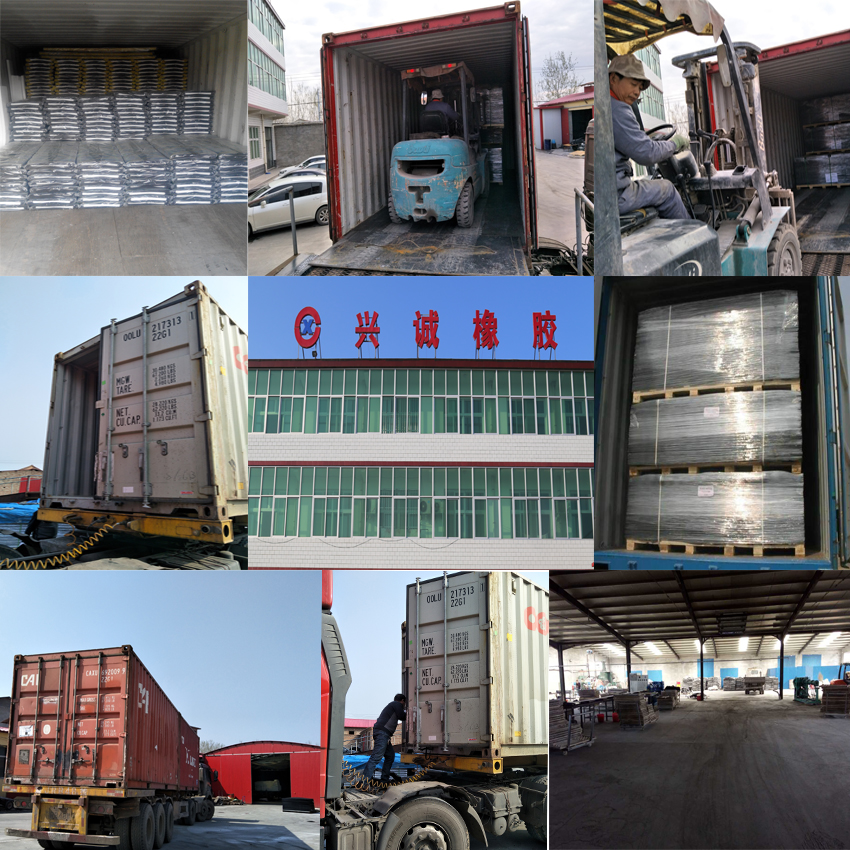
Company information:
RenqiuXingcheng Rubber Products Co., Ltd. is located in the side of the Baiyang lake, our company is professional manufacturer of rubber products. We are one of the leading rubber company in china,The company is a private enterprise which is engaged in scientific research, production, sales and service and has obtained ISO 9001 certification. Our main business is producing all kinds of rubber products, including anti-skid plates, Rubber Sheet Series, Rubber Mat Series and horse mat series ect., The products are shockproof, anti-wear, anti-high and low temperature, anti-aging, oil resistant and chemical resistant in character.At present, our products have been sold at home and abroad and mainly exported to Canada, Germany, Chile, etc. We welcome domestic and foreign merchants to negotiate and cooperate with us. We are willing to join hands with old and new friends in creating a better tomorrow.

Rubber Mat
Rubber Mat,Livestock Rubber Mats,Animal Rubber Mat,Anti-Fatigue Rubber Mat
Renqiu Xingcheng Rubber Products Co., Ltd. , https://www.xingchengrubber.com