
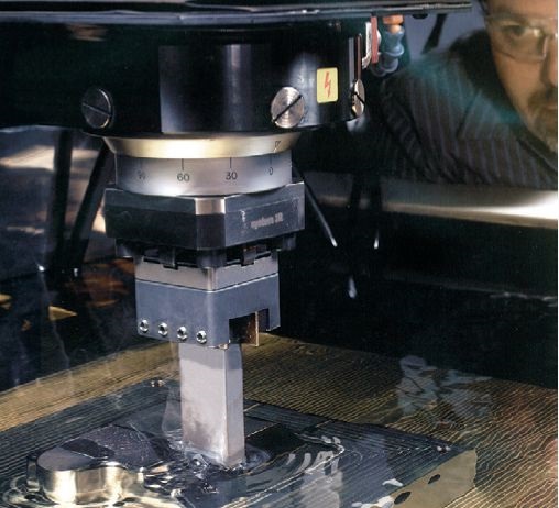
At present, mirror EDM technology has been gradually promoted in the manufacture of precision cavity molds. In this paper, the key factors in the application of mirror EDM in the enterprise are combined with practice to analyze the factors affecting the performance of mirror surface processing. At present, mirror EDM technology has been gradually promoted in the manufacture of precision cavity molds. In this paper, the key factors in the application of mirror EDM in the enterprise are combined with practice to analyze the factors affecting the performance of mirror surface processing. By controlling various process steps, high-quality, high-efficiency mirror EDM can be effectively realized. It has practical application value for mold manufacturing enterprises to absorb and digest the current advanced EDM process.
1 Introduction
At present, the rapid development of mold manufacturing technology has given higher requirements for EDM. Surface roughness is an important technical indicator for EDM. At present, mirror EDM can be realized through the improvement of machine tools and the development of new processes. The so-called mirror EDM generally refers to the processing surface roughness Ra
2. Key application technology of mirror EDM
The following is a discussion of the key technologies for mirror EDM applications based on practical processing experience.
2.1 Relationship with workpiece materials
Due to the difference in chemical composition and structure of the workpiece material, different processing effects are produced under the same processing conditions. Some materials can achieve good mirror effects, while some materials do not have mirror effects, and even the surface has streaks and other anomalies. Table 1 lists the EDM performance of a variety of common workpiece materials. It should be noted that the material that is not good in EDM mirroring indicates that it is not a mirror material. For example, S136 ESR steel itself has excellent polishing performance, but the mirror effect using EDM is not ideal. EDM and polishing are two completely different processing methods. The surface of the EDM is composed of a plurality of disc-shaped pits which overlap each other. These tiny pits form a glittering mirror surface under the reflection of light. The microscopic pits produced by different materials after EDM are different. The brightness of the surface is also different.
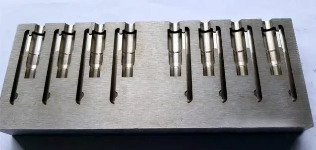
Table 1 EDM surface processing performance of common workpiece materials
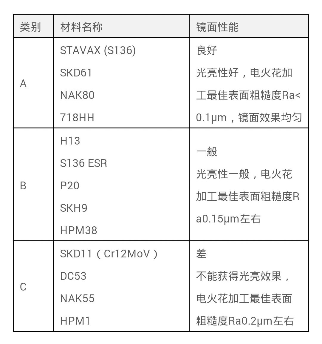
The following can be considered as some of the reasons why the workpiece material affects the mirror finish:
(1) coarse carbide or coarse crystal particle inclusions containing large particle diameters are disadvantageous for processing mirrors, resulting in microcracks;
(2) The silicon-containing component is favorable for obtaining a good mirror effect;
(3) Sulfur S containing a fast-cut component is unfavorable for processing mirrors, and is prone to surface streaks;
(4) The manufacturing process factors such as the rolling direction of the material are unfavorable to the processing of the mirror surface, resulting in surface streaks;
(5) Metal inclusions, bubbles, oxides and other factors form pinholes and holes.
Generally speaking, most plastic mold steels can meet the requirements of mirror EDM, and most cold work die steels cannot be satisfied.
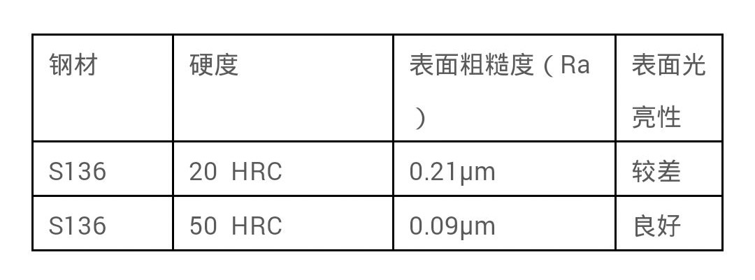
When the performance of the material satisfies the mirror EDM performance, the higher the hardness, the better the effect of the EDM mirror, as shown in Table 2. It is generally required that the mirror EDM steel should be hardened by heat treatment to HRC>50.
Table 2 Comparison of the influence of material hardness on mirror surface effect
2.2 Relationship with processing area and cavity type
The mirror effect of EDM is directly related to the processing area, shape and depth.
Since the surface roughness of EDM is mainly dependent on a single pulse energy, a reflective surface with a low surface roughness can be produced by reducing the spark discharge energy of a single pulse, but mirror processing is limited to small area processing. As the processing area increases, the parasitic capacitance between the electrode and the workpiece increases accordingly. When a single small energy discharge pulse acts between the two poles, it does not cause a spark discharge between the two poles. At this time, the gap voltage rises very much. Slow, the pulse energy is stored in the parasitic capacitance. Only when a plurality of discharge pulses arrive, and sufficient energy is stored in the parasitic capacitance, the gap voltage gradually rises to the breakdown voltage, causing the spark discharge, but the discharge at this time. The energy is equivalent to the superposition of multiple discharge pulse energies, and the generated discharge pit depth will be greatly increased, the surface roughness value will become larger, and the processed surface will lose the mirror effect.
In order to achieve large-area mirror EDM, by adding a certain amount of powder to the working fluid, the surface roughness after EDM can be significantly improved, achieving a mirror-like effect, and a faster processing speed can be obtained. Finishing time is reduced by 20%-30%).
In the case where the powder mixing process is not used, the larger the processing area, the more difficult it is to obtain a good mirror effect. In fact, due to the application of the translation process, the electrodes are not in contact with the entire area. This partial discharge reduces the "capacitance effect" and additionally produces a uniform layer of carbon black between the electrode and the workpiece during the discharge process. The layer, its function is similar to the meaning of powder mixing processing, so a larger processing area (such as 1600mm2) can achieve a uniform mirror effect by optimizing the process parameters. For the case of using the powder mixing process, it is easy to achieve a large-area (such as 10000mm2) mirror effect.
From the perspective of the processed shape, a simple shape is easier to obtain a mirror than a complicated shape. The shape that is most likely to obtain a mirror effect is a circle, followed by a square shape with a complicated contour. The most difficult type is the overall discharge type of multiple cavities. The mirror surface effect of the corners and curved surfaces of complex shapes is more prone to unevenness and ripples.
Judging the difficulty of the mirror surface processing can also refer to whether the carbon black layer produced by the discharge can uniformly cover the surface of the electrode and the workpiece. For example, the bottom surface is easier to obtain a good mirror effect than the side surface. This is because the bottom surface is always in a state of being trimmed during the entire discharge process, and the carbon black layer can be uniformly distributed on the processing surface, but the side surface is completed by translation processing. The black layer cannot be effectively covered with respect to the bottom surface. In addition, the cavity having a larger depth is affected by the uniformity of the mirror effect because the processed portion cannot uniformly cover the carbon black layer.
2.3 Mirror processing database
The configuration content of the EDM process database mainly includes electrical specifications and reservations. A set of mirror EDM database consists of up to a dozen electrical standards. From roughing electrical gauges to finishing electrical gauges, a reasonable transitional electrical gauge is required to gradually reduce surface roughness. Each gear gauge should be able to discharge stably without causing undesirable surface conditions such as arcing and carbon deposition. At the same time, a reasonable margin needs to be reserved between every two electrical standards. The latter electrical standard is required to repair the discharge pits generated by the previous electrical standard. Only by perfectly matching the electrical specifications and the reserved quantities to build a processing database can mirror processing be realized in actual production.
The electrical specifications include parameters such as current, pulse width, pulse gap, polarity, voltage, and lift control. The electrical standard in the roughing stage uses a large peak current and pulse width, a small pulse gap, and the positive polarity (the electrode is positive) to achieve high efficiency, low loss processing, fast lifting speed, and help to remove chips. . The current in the middle machining stage is sequentially reduced. In order to reduce the surface roughness value and achieve stable electric discharge machining, the pulse width is greatly reduced. Since the rough machining stage has removed most of the machining amount, the relative loss in the middle machining stage is not Big. In the finishing stage, the negative polarity processing (electrode is the negative electrode) is usually used below the VDI18 (Ra0.8um) standard, and the smaller pulse width is used to discharge through the capacitor energy storage, thus achieving the maintenance in the finishing stage. High efficiency and discharge stability. In order to avoid defects such as surface black spots, the electrical rules in the finishing stage use large veins to achieve a uniform matte finish surface.
When the finished surface reaches the VDI12 level (Ra 0.4μm), it can be switched into mirror processing. The effect of mirror processing depends on the configuration of the last gear. Theoretically speaking, the mirror EDM should be configured with small peak current, small pulse width and large pulse gap. The smaller the peak current is selected, the smaller the pulse width is, the larger the pulse gap is, and the machined surface is processed. The smaller the roughness value. In fact, with this parameter matching method, the processing efficiency is extremely low, and the pulse energy that is too small cannot obtain a uniform mirror effect due to the inability to stably discharge. For actual mirror processing, a larger peak current and a smaller pulse width should be used, and a larger peak current makes discharge breakdown under a small pulse width condition easier. Mirror EDM is processed by negative polarity (electrode is negative) and cannot be used with capacitors. In addition, the selection of the lift control parameters is also very important, and there are some differences with the choice of conventional machining. For example, the discharge time should be longer, the height of the lift should not be too high, and the lift speed should not be too fast. The purpose of this setup is to A uniform layer of carbon black can be formed between the electrode and the workpiece to maintain a stable electrolytic corrosion process, and the tooling action of the machine will interfere with the formation of the carbon black layer.
The amount of reservation between the electrical standards affects the processing speed and surface roughness. Smaller reserves are more efficient to machine, but they can cause the surface to be repaired. The most ideal processing condition is that after the first condition is processed, the subsequent processing is only to repair the surface unevenness formed by the first processing condition without destroying the new material. However, in actual processing, considering the constraints of the discharge condition, the safety reserve is considered. The processing efficiency of VDI18 and above is mainly determined by the reserve between the various standards. The electrical specifications of VDI18 and below are basically only due to the weakening of the electrical erosion. The size of the processing is performed, and the processing takes a long time. In fact, as long as the required surface roughness is processed, the machining can be finished. Therefore, the numerical control EDM machine can effectively control the machining efficiency through the timing processing function for the finishing standard, that is, the setting of the repair for each gear. Light time.
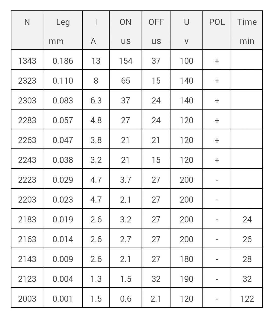
The electrical calibration method of the advanced CNC EDM machine is intelligent, and the machining process data can be automatically generated by the expert system. When programming, select the material pair, application type, surface roughness value, input processing area, machining depth, electrode size scaling, etc., the machine tool can be configured to process electrical specifications.
Table 3 Data sheet of an advanced machine tool mirror processing (part)
2.4 translation process
The translation function of the numerical control EDM machine tool, the electrode is continuously processed in the shaking along the target processing shape, eliminating the stagnation of the electrode, and achieving the uniform surface effect of the bottom surface and the side surface of the cavity. In a process that does not use a translational process, even a small area of ​​10 mm in diameter is difficult to achieve a uniform high-gloss mirror effect. The application of the translational process avoids concentrated contact discharge of the entire area of ​​the electrode, and a large area of ​​mirror processing can be realized by periodic partial discharge.
Mirror EDM requires the selection of a suitable translation. For most of the cavity mirror EDM, the amount of translational motion of each gauge can change simultaneously with the depth, that is, the depth is gradually increased, the translational amount is also increased, and the bottom surface and the side surface are simultaneously processed. Linkage mode. This translational method significantly improves the stability of the machining in the finishing of small energy. Since the bottom surface and the side surface are processed simultaneously, the timing processing function can be effectively activated to realize the surface of the side surface and the bottom surface within the specified processing time. Uniform effect.
2.5 relationship with the electrode
Mirror EDM uses a multi-electrode replacement process. It is necessary to determine the processing using several electrodes depending on the amount of processing of the processed portion. Generally, two electrodes are used for roughing and finishing. The size of the roughing electrode is 0.25 mm on one side, and the size of the finished electrode is 0.15 mm on one side. When the processing area is small or the precision of the contour is high, it may be smaller. The roughing electrode uses a large discharge energy to quickly remove a large amount of metal, and the surface can reach VDI28 (Ra2.5μm), usually leaving a margin of about 0.07mm; the finishing electrode is gradually thinned, and finally the mirror processing . If the cavity has been pre-milled and the machining volume is not large, the mirror-to-spark machining from coarse to fine can be done with one electrode.
The coarse and fine processing requires the consistency of the electrode to be good, the manufacturing precision to be high, the repeated clamping of the replacement electrode, and the positioning accuracy to be high. High-speed milling can be used to fabricate electrodes, positioning methods using reference spheres, and 3R rapid-clamp positioning systems for repeat positioning to meet high demands.
Mirror EDM requires the use of high purity copper as the electrode material (such as Japan's Sambo red copper), which has good processing performance, is less prone to arc discharge, and can obtain a uniform processing surface. If the purity of the copper electrode material used is insufficient, the mirror surface unevenness and local defects may be caused.
The mirror-finished electrodes must be polished (at least by 1000# sandpaper) to achieve a low surface roughness. If there are corrugations and defects on the surface of the electrode, it does not affect the brightness of the surface of the machined surface, but the surface roughness value will be larger than Ra0.2μm. In the mirror EDM process, the micro-period motion of the electrode in the XY plane can effectively equalize the microscopic defects on the electrode surface, which is beneficial to reduce the roughness of the machined surface. According to the processing experience, when the surface roughness of the electrode is Ra 0.25 μm, the mirror processing effect of Ra 0.1 μm can be achieved.
2.6 Relationship with working fluid
The electric spark working fluid plays the role of eliminating ionization, cooling and eliminating electrocautery products during the processing. The working fluid should be selected according to the requirements of EDM. The main reference is the “viscosity†index. The oxidation resistance and thermal stability are also critical to determine the service life of the oil. The low viscosity is beneficial to the flow of the working fluid in the processing gap, and the heat generated by the etching and the processing is taken away, so that the processing gap returns to the normal state in time. The viscosity of the working fluid used for mirror EDM is recommended to be 2 to 3 mm2/s. It is recommended to use the spark oil TOTAL EDM 22 (kinematic viscosity (40 ° C) 2.4 mm 2 / s; flash point 102 ° C).
Powder-mixed EDM has added a certain amount of powder particles to the working fluid. According to the technical reports of many mixed powder processing at home and abroad, there are several kinds of silicon powder, aluminum powder, magnesium powder and graphite powder. The powder used in the FORM20 machine tool is a special mixed powder solution researched by GF Processing Solutions. Its composition is mainly graphite particles, the approximate length is less than 8um, and the concentration of powder added is 2g/L. Every time before changing the mixing liquid, it is necessary to filter and clean the spark oil, filter the residue and the powder in the process and then add the powder mixture solution to ensure the processing time is 350 to 400 hours. When the concentration of the mixed powder is not enough, the surface gloss effect cannot be achieved in a short time. When the mixed powder concentration is too large, the sharp edges and corners of the cavity will be destroyed, and more powder exists between the electrode and the workpiece. It can cause a short circuit in the flow and, in severe cases, can cause scratches on the surface of the workpiece.
2.7 Mirror processing
CNC EDM is generally based on oil immersion processing with appropriate pressure side flushing to help efficient chip removal to improve processing efficiency. In the mirror EDM process, the side flushing liquid cannot be used, and the working fluid can be set to a slight circulation state. The flushing force of the side flushing fluid will destroy the carbon black layer between the electrode and the workpiece, which affects the uniformity of the mirror surface processing effect.
In the mirror EDM process, it is often able to maintain a high stable discharge state, and generally does not produce carbon deposits. Therefore, it should be stopped as much as possible during the processing, especially if the powder layer of the workpiece processing surface is not cleaned, otherwise it will be serious. Affects the ongoing processing of the mirror finish.
When the mirror finish is not satisfactory after processing, do not remove the workpiece and use the mirror electrical gauge for refining. During the refinement, it is found that the discharge state is very unstable, and the electrode delay cannot enter the overall discharge state. In this case, first use the air gun to completely blow the electrode and the carbon black layer on the surface of the workpiece, then start the discharge, and increase the voltage value to 200V ~ 250V. After the voltage is increased, the discharge breakdown becomes easy. In just a few minutes, it can be observed that the discharge state is transferred from the partial discharge to the overall discharge, and then the voltage value is restored to the normal value. In this process, a carbon black layer is regenerated between the electrode and the workpiece, and a uniform carbon black layer needs to be formed in the entire processing portion to complete the processing.
3, the conclusion
In summary, by selecting the appropriate workpiece material, high-purity copper electrode material, low-viscosity working fluid, using the appropriate translation process, and rationally configuring the process database, correctly process the process, and grasp these key applications. The link can effectively achieve high-quality, high-efficiency mirror EDM, which has important guiding significance for improving the craft level of mold manufacturing enterprises.
Http://EDM.html
Http://news.chinawj.com.cn
 Editor: (Hardware Business Network Information Center) http://news.chinawj.com.cn
The Tinhy's Geocell of geosynthetic cellular confinement system is a matrix of lightweight, expandable and flexible thermoplastic strips that are ultrasonically bonded to form a strong, dimensionally stable and inert honeycomb structure.
The geocell is honeycombed three-dimensional grid structure which is welded by high-strength HDPE sheet. The geocell is easy to stretch. It can be folded up when transport and opened to fill the earth or concrete when use it. It will constitute a strong lateral and large stiffness of the structure when use it. In the geotechnical engineering, soil, sand, stone, concrete and other fill together constitute a different cohesion, different reinforcement strength, different depth of the cushion. The cushion can be placed in the required position accordance with the requirements of the project for Reinforcement of roads, railways and soft soil foundation, slope protection, green structure, the construction of retaining walls and so on. The most important feature is can solve and complete a variety of difficult problems which can`t be dealed with use conventional method in geotechnical engineering,such as bridge jumping, soft base subsidence, fouling, landslides and desert subgrade.


Appliction:
The geocell is honeycombed three-dimensional grid structure which is welded by high-strength HDPE sheet. The geocell is easy to stretch. It can be folded up when transport and opened to fill the earth or concrete when use it. It will constitute a strong lateral and large stiffness of the structure when use it. In the geotechnical engineering, soil, sand, stone, concrete and other fill together constitute a different cohesion, different reinforcement strength, different depth of the cushion. The cushion can be placed in the required position accordance with the requirements of the project for Reinforcement of roads, railways and soft soil foundation, slope protection, green structure, the construction of retaining walls and so on. The most important feature is can solve and complete a variety of difficult problems which can`t be dealed with use conventional method in geotechnical engineering,such as bridge jumping, soft base subsidence, fouling, landslides and desert subgrade.

1.soil retention --earth walls
2.load support --roadways and verges
--sidewalk
--railway batses
3.slope protection --vegetative slope
--road side banks
--embankment
4.channel protection --embankment walls
--waterway channels

Specification:
Item No.
Hight
Weld distance
Thickness of the Sheet
Tensile Strength of Welding Points
Tensile Strength of Connection of Cells
Tensile Strength at Yield of Each Sheet
GS-50-400
50
330≤A<1000
≥1.1
≥100
≥120
≥20
GS-75-400
75
330≤A<1000
≥1.1
≥100
≥120
≥20
GS-100-400
100
330≤A<1000
≥1.1
≥100
≥120
≥20
GS-150-400
150
330≤A<1000
≥1.1
≥100
≥120
≥20
GS-200-400
200
330≤A<1000
≥1.1
≥100
≥120
≥20
(mm)
(mm)
(mm)
(N/cm)
(N/cm)
(N/mpa)
Packing:


Geocell
Plastic Hdpe Geocell For Road,Plastic Honeycomb Hdpe Geocell,Plastic Geocell,Hdpe Geocell
Shandong Tianhai New Materials Engineering Co., Ltd , https://www.chinatinhy.com